Basement Finishing Plans: Blueprints for Your 2026 Build
Browse basement finishing plans with layouts, code requirements, and design ideas. Start your 2026 renovation with templates that meet your needs.
By Excellent Home Improvement

The popular advice is to start with the fun part, choose a theater, bar, guest room, or gym, then fit the technical work around it. That order creates expensive problems. Basement finishing plans should begin with the building envelope, moisture control, and code path, because those conditions determine where walls, wiring, flooring, ceilings, and bedrooms can safely go.
A basement is not just an unfinished interior. Its concrete foundation walls, slab, rim-joist band, drainage system, and utility routes form a below-grade enclosure. If the plan ignores that enclosure, a beautiful layout can fail during permit review, rough inspection, or the first wet season.
National benchmarks put a basement finishing project at about $32,000 on average, with many homeowners spending $15,000 to $75,000. Basic finishing is often described at roughly $7 to $23 per square foot, while a full remodel can reach $30 to $90 per square foot. The commonly summarized 2025 Cost vs. Value benchmark places basement remodel cost recovery at about 71%, so a $50,000 project might contribute roughly $35,000 in resale value rather than returning every dollar (basement renovation cost and resale benchmarks).
Table of Contents
- Why Basement Finishing Plans Start With the Envelope
- Anatomy of a Complete Basement Plan Set
- Moisture Control as a Drawing Requirement
- Framing Plans for Basement Walls and Soffits
- Egress Planning and Window Well Details
- Insulation Strategies Compared Side by Side
- Electrical Plans That Pass Inspection
- Sample Room Configurations and Layout Sketches
- Designing for Future Flexibility
- Quick Reference Checklist Before You Finalize Plans
- Frequently Asked Basement Finishing Plan Questions
Why Basement Finishing Plans Start With the Envelope
A room layout is only useful after the basement can support a durable finish. Before drawing a partition, confirm that exterior grading, footing drainage, damp-proofing, foundation cracks, sump operation, and slab conditions are understood. If water has an entry path, framing and drywall will only hide the evidence until the damage becomes harder to correct.
The correct sequence is straightforward:
- Investigate water movement. Look for active leakage, staining, efflorescence, musty areas, and cracks. Verify how perimeter drainage and sump discharge work.
- Confirm the slab assembly. The plan should identify the slab, vapor retarder, sealed penetrations, and the relationship between the slab edge and foundation wall.
- Resolve insulation and condensation risk. Foundation insulation belongs at the perimeter, not between basement floor levels. Cold concrete surfaces need insulation that won't create a moisture trap.
- Draw the code constraints. Establish ceiling heights, fire blocking, stair protection, mechanical access, and egress before placing furniture or built-ins.
- Lay out framing and services together. Stud walls, HVAC ducts, drain lines, electrical boxes, and access panels must occupy the same coordinated drawing.
Practical rule: If the wall section isn't resolved, the floor plan isn't ready.
This is why a planned theater often causes trouble. A homeowner may center a screen on a foundation wall, only to discover that the only practical sleeping-room location needs an egress opening there, or that a duct requires a soffit that reduces usable ceiling height. The plan set exists to expose those conflicts before construction, not after the drywall is installed.
Anatomy of a Complete Basement Plan Set
A permit-ready package is more than a furnished floor plan. Each sheet answers a different construction or inspection question, and the sheets must agree.
The drawings that establish existing conditions
The cover sheet records the project scope, applicable code information, occupancy assumptions, and construction notes. The existing-conditions plan should show foundation walls, columns, beam pockets, stairs, windows, cleanouts, sump pits, water heaters, furnaces, ductwork, plumbing penetrations, and electrical equipment. If anything is removed, a demolition plan identifies it clearly instead of leaving the crew to interpret the layout.
The proposed floor plan then adds dimensioned partitions, door swings, room names, built-ins, plumbing fixtures, and clearances. The framer uses it to locate plates and openings. The inspector uses it to understand room use and access. The homeowner uses it to verify that the finished space still provides access to shutoffs, filters, drains, and equipment.
The sheets trades actually build from
A coordinated set typically includes:
- Framing plan: Shows wall types, stud layout, headers, treated bottom plates, blocking, chases, and soffit framing.
- Reflected ceiling plan: Locates ceiling changes, beams, bulkheads, recessed fixtures, access panels, and lighting zones.
- Electrical plan: Identifies receptacles, switches, lighting controls, dedicated circuits, alarms, and protection notes.
- Mechanical plan: Shows supply and return locations, duct routes, combustion-air requirements where applicable, equipment clearances, and dehumidification provisions when specified.
- Egress elevations: Documents window or door dimensions, sill height, well geometry, ladder or step provisions, and drainage.
- Wall sections: Shows the complete assembly from foundation to finished wall, including insulation, vapor control, capillary breaks, slab buildup, and fire protection.
The most common coordination failure is a wall that appears on the architectural plan but disappears on the mechanical or electrical sheet. A chase gets framed without an outlet, a drain line runs through a future cabinet, or a soffit covers a required access point. Plumbing, framing, electrical, and HVAC drawings need to be reviewed as one package, not as separate trade sketches.
Moisture Control as a Drawing Requirement
“Waterproof the basement” isn't a sufficient plan note. A useful set identifies where water is managed, how vapor movement is limited, and which materials remain compatible with the below-grade environment.
The foundation detail should identify exterior damp-proofing or waterproofing where work is being performed, along with drainage at the footing. The floor plan should locate the sump, cleanouts, floor drains, and any interior drainage channel. The wall section should show a continuous capillary break between the concrete slab and the treated bottom plate, usually through a sill gasket or equivalent separation.
For slabs, the vapor retarder belongs directly beneath the concrete and should meet ASTM E1745 Class A, B, or C. Insulation vapor control is commonly evaluated using ASTM E96, with Class I vapor retarders defined at 0.1 perm or less. The relevant assembly details and material guidance are set out in basement insulation and moisture-control guidance.
What belongs in the specifications
Call out sealed vapor-retarder laps, turned-up edges at wall intersections, sealed pipe penetrations, and the intended drainage route. If the foundation has a history of leakage, specify the repair or mitigation method before framing begins. Don't bury an active crack behind insulation and hope the interior finish will solve it.
A simple plastic-sheet test can help identify vapor migration through the slab before flooring is selected, but it isn't a substitute for diagnosing active water entry. Flooring, adhesives, wall insulation, and trim all need to suit the measured conditions.
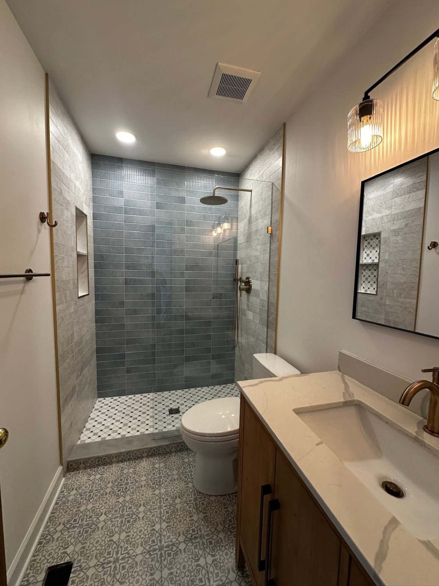
If the basement includes a bathroom, wet bar, or utility sink, show the waterproofing boundaries and drain access on the plumbing and wall details. A resource on basement waterproofing systems can help organize the product discussion, but the plan still needs to identify the actual layers and transitions.
Moisture control is complete only when the drawing shows continuity, not merely a product name.
Framing Plans for Basement Walls and Soffits
The framing sheet turns the basement concept into buildable geometry. It should distinguish foundation-adjacent walls, freestanding partitions, furring assemblies, utility chases, and soffits. That distinction matters because each wall type handles insulation, fastening, access, and moisture differently.
Bottom plates installed over a concrete slab generally need treated lumber, with a capillary break between wood and concrete. The plan should identify plate material, anchor or fastening method, wall thickness, and any required separation. Stud spacing is commonly shown at 16 inches on center, but the drawing should state the actual layout rather than leaving it to field judgment.
Framing decisions that affect every trade
Use thinner walls where space is tight and deeper walls where insulation, conduit, plumbing, or acoustic separation requires additional cavity depth. A 2x4 and a 2x6 wall aren't interchangeable on a plan because they change finished dimensions, door jambs, outlet box depth, trim returns, and available insulation.
Box-outs deserve their own call-outs. Mark locations around:
- Supply and return ducts
- Main drain lines and cleanouts
- Beam pockets and structural posts
- Electrical panels and subpanels
- Water heaters, furnaces, and service clearances
- Future plumbing chases
- Stair undersides and access doors
Soffits should be drawn from actual duct and pipe dimensions, not estimated rectangles. A soffit that looks harmless on the reflected ceiling plan may reduce a bedroom or circulation area below the required finished ceiling height. Typical code checks call for a 7-foot minimum finished ceiling height, while fire blocking is commonly required at top plates, dropped ceilings, and horizontal intervals not exceeding 10 feet. The applicable local code controls, but the plan should make the intended protection visible.
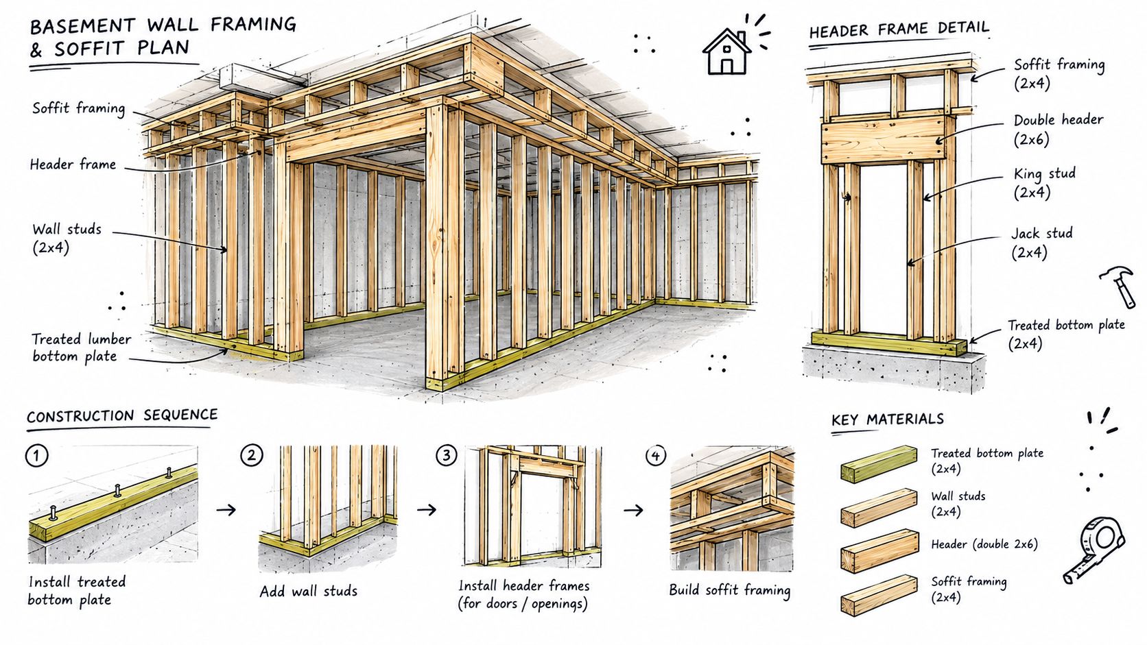
Show nailing into concrete, pressure-treated lumber locations, fire blocking, backing for cabinets or grab bars, and framing around access panels. When the drawings are complete, the crew can install professional drywall work without discovering that a chase, box, or support was omitted.
Egress Planning and Window Well Details
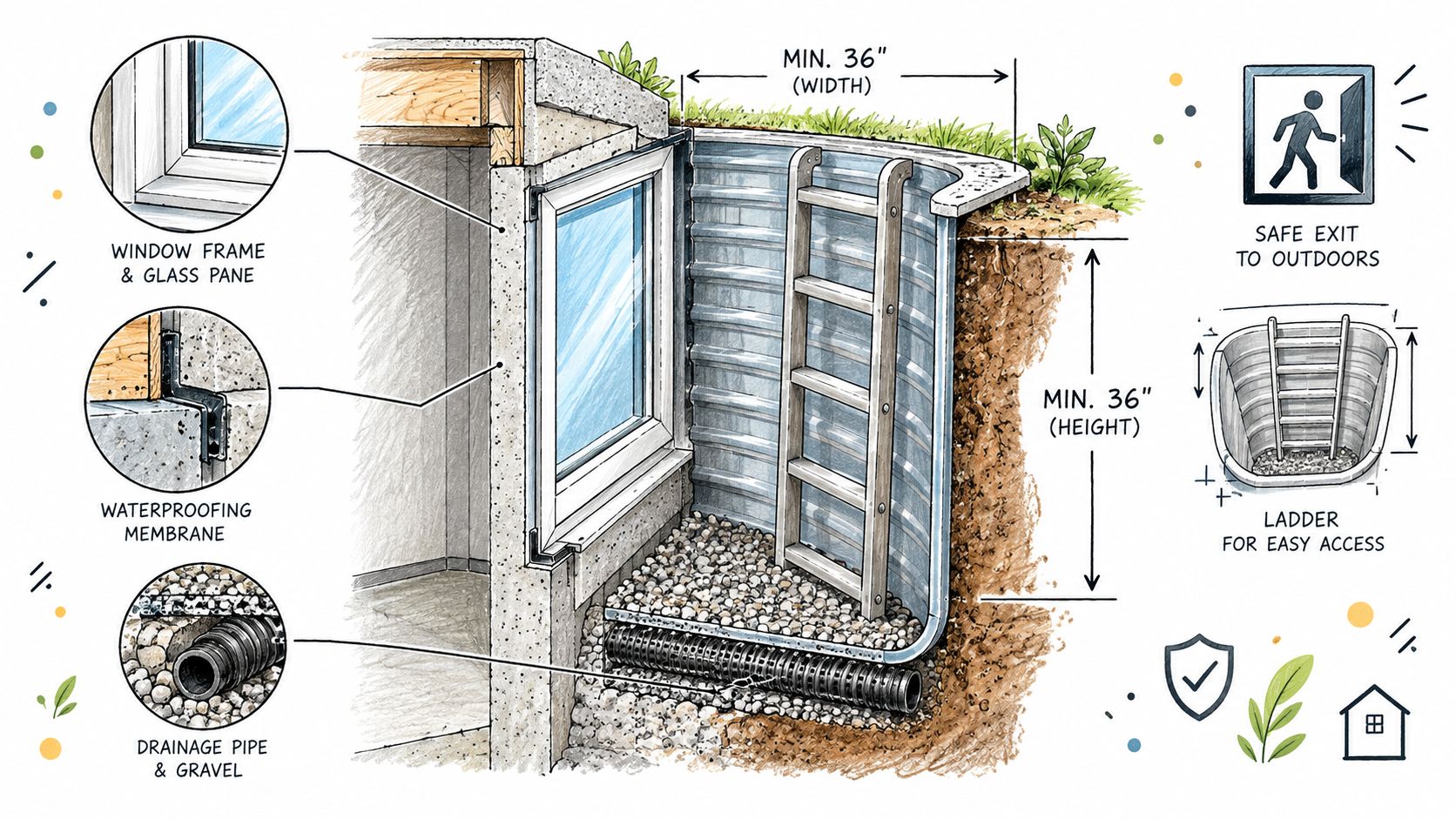
Egress is the detail that changes a basement room from private storage or recreation space into a potential sleeping room. Under typical IRC-based requirements, a sleeping room needs an operable emergency escape and rescue opening with a minimum 5.7 square feet of clear opening, a minimum clear height of 24 inches, a minimum clear width of 20 inches, and a sill no more than 44 inches above the floor. These figures and the conditions for below-grade openings should be confirmed with the local authority having jurisdiction.
The plan elevation must show net clear opening, not the overall glass or frame size. Casement and sliding windows produce different clear openings, so the selected unit needs to be identified before the elevation is finalized.
What the window well drawing must include
For a below-grade opening, show:
- A window well projecting at least 36 inches from the foundation wall
- A ladder or steps when the well is deeper than 44 inches
- A clear route from the window to grade
- A bottom surface that drains
- A connection to the foundation drainage system or daylight drainage where permitted
- A cover only when it doesn't obstruct emergency escape
A walkout basement may use an egress door with direct access to grade, but the plan still needs to show the route, door operation, landing, and room classification. Existing basements generally don't require egress openings unless the project creates new sleeping rooms. That distinction should be written into the room schedule so the reviewer understands why an opening is or isn't shown.
Insulation Strategies Compared Side by Side
Basement insulation isn't a simple product selection. It changes the wall thickness, vapor-control notes, fastening method, fire protection, and finished floor area. The assembly must also suit the foundation's moisture history.
The table below is a planning comparison, not a substitute for the local energy code or manufacturer data. R-values vary by product thickness and installation, so the final plan should list the specified assembly rather than relying on a generic label.
Basement wall insulation compared
| Strategy | Typical R-Value | Vapor Control | Fire Performance | Below-Grade Suitability |
|---|---|---|---|---|
| Closed-cell spray foam against foundation | Product- and thickness-dependent | Can provide strong vapor control when installed continuously | Requires approved thermal or ignition protection | Useful where a continuous foundation-side air and vapor control layer is appropriate |
| Rigid foam board with framed stud wall | Board thickness-dependent | Board selection and joints control vapor behavior | Usually requires interior protection | Suitable when joints, edges, and transitions are detailed carefully |
| Fiberglass batts in stud cavity over a separate vapor barrier | Cavity-depth dependent | Depends heavily on correct barrier placement and continuity | Requires protected interior finish | More sensitive to moisture and air-leakage mistakes |
| Mineral wool in a stud cavity | Cavity-depth dependent | Usually needs a separately designed vapor-control layer | Naturally noncombustible, but still needs required finish protection | Can work in a properly detailed, dry assembly |
A rigid-board assembly may reduce thermal bridging but requires careful detailing at seams, corners, slab edges, and penetrations. Spray foam can conform to irregular concrete, yet it still needs protection and professional installation. Fiberglass and mineral wool depend more visibly on a complete framed assembly, which means the wall section must show the vapor-control layer and its warm-side location where permitted.
Don't omit the rim joist. It's often the weakest thermal transition in the basement enclosure and needs its own insulation, air-sealing, and fire-protection detail. The same drawing should show how the rim-joist treatment meets the foundation wall and the floor framing above.
Electrical Plans That Pass Inspection
An electrical plan should answer three questions before wire is pulled: does the panel have capacity, what loads need their own circuits, and how will protection be provided? Start with a load review and identify whether the existing service and panel can support the proposed work. A basement with lighting, general receptacles, a sump, HVAC equipment, a bathroom, and a wet bar may need more coordination than an open recreation room.
Separate the plan into general lighting, general receptacles, dedicated appliances, sump or HVAC equipment, and any bathroom or bar loads. Show smoke and carbon monoxide alarms where required, including interconnection notes when the code demands that alarms operate together.
Electrical circuit planning at a glance
| Circuit Type | Typical Amperage | Required Protection | Plan Sheet Note |
|---|---|---|---|
| General lighting | Confirm by load calculation | Local code may require AFCI protection | Identify zones, switches, dimmers, and three-way controls |
| General receptacles | Confirm by load calculation | GFCI and AFCI protection where required | Show wall spacing, built-in conflicts, and accessible locations |
| Dedicated appliance | Appliance-specific | GFCI, AFCI, or other protection as applicable | Name the appliance and reserve the correct outlet location |
| HVAC or sump | Equipment-specific | Protection required by equipment and local code | Show disconnects, service access, and backup provisions where designed |
Coordinate outlet heights with wainscoting, cabinetry, media walls, and built-ins. Coordinate panel or subpanel locations with framing so the electrician doesn't face a post, duct, or future door swing. The rough inspection will also focus on box fill, cable support, nail-plate protection, labeling, and disconnect access.
Lighting zones should match the reflected ceiling plan. A theater, office, gym, stair, bathroom, and utility room shouldn't be treated as one undifferentiated switch circuit. Review fixture locations and controls with the basement lighting and fixture planning options before the ceiling is closed.
Sample Room Configurations and Layout Sketches
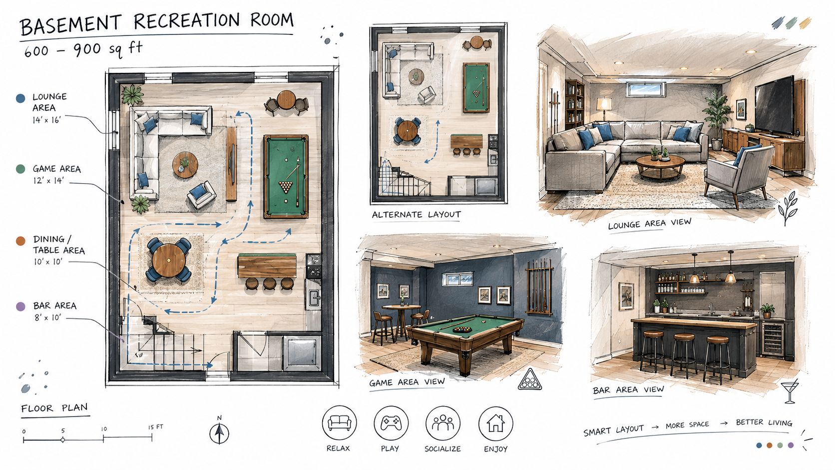
A flexible basement plan works best when the room use is tested against the technical requirements. The sketches below represent common planning patterns for a basement in the 600 to 900 square foot range, but the actual dimensions, structural conditions, and local code determine whether a layout works.
Open recreation room
[ Egress-capable exterior wall ]
|             REC ROOM             |
|   media wall       flexible use  |
|                                  |
| stairs | utility access | storage |
Keep the room open, use one primary lighting zone, and avoid unnecessary plumbing. Positioning an egress-capable opening in the family area can preserve future conversion options without committing the room to a bedroom today. The framing plan should still show backing for media equipment and storage.
Home office
[ Natural light / opening ]
| OFFICE        | equipment wall |
|               |                |
| sound-rated partition | stairs  |
The office needs a dedicated equipment circuit, carefully placed receptacles, and sound-control notes in the wall section. Natural light helps the room function as a workspace and may support ventilation assumptions, but it doesn't replace mechanical requirements. Keep the desk wall clear of ducts and provide a route for data or communications wiring.
Guest suite
[ Egress window well ]
| SLEEPING ROOM | BATHROOM       |
|               |                |
| door          | vent / plumbing|
|------- hall and access ----------|
This is the most code-intensive arrangement. The sleeping room needs its own compliant egress opening and alarm coordination. The bathroom adds plumbing, ventilation, waterproofing, lighting, and electrical annotations, while the hallway must preserve a practical path to the stairs.
Wet bar
| REC AREA       | BAR            |
| media          | sink  fridge   |
|                | GFCI outlets   |
| stairs         | plumbing chase |
A wet bar pulls the plumbing rough-in toward a drain and supply route. Reserve a dedicated circuit for the beverage refrigerator and show GFCI protection where required. Keep cleanouts and shutoffs accessible instead of hiding them behind permanent cabinetry.
Home gym
| OPEN TRAINING AREA             |
| reinforced wall for equipment  |
| mirrors                         |
| storage | equipment circuit     |
| stairs and utility access       |
A gym plan needs wall reinforcement where mirrors, racks, or pull-up equipment will attach. The flooring specification should suit impact and moisture conditions, while the electrical plan should identify equipment loads. Leave circulation around machines instead of filling the room to its drawn limits.
Designing for Future Flexibility
The most useful basement finishing plans serve the next owner as well as the current household. That doesn't mean building every possible room now. It means preserving the few conditions that are difficult or expensive to change later.
Protect the hard-to-change decisions
Ceiling height comes first. Route ducts, beams, and drain lines so a future sleeping room won't be trapped beneath an avoidable low soffit. A bulkhead placed across the wrong part of the plan can turn a flexible room into a permanent passage.
Utility chases matter just as much. Reserve a route for future bathroom drainage, water supply, electrical expansion, and HVAC distribution. A rec room can remain open today while the plan labels a future plumbing zone and protects access to it.
Egress is the other major lock-in. Creating a suitable opening and well during the current construction phase is usually simpler than cutting a finished concrete foundation later. Mark future bedroom locations, future door swings, and possible furniture arrangements on the plan, even if the initial permit covers only recreation space.
Labeling matters. Add notes such as “future sleeping room,” “future bathroom chase,” or “maintain access to panel and cleanout.” Those notes give the next contractor and reviewer a clear record of intent without claiming that an unbuilt room is already legal habitable space.
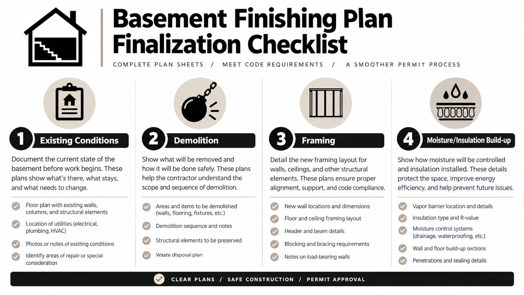
Quick Reference Checklist Before You Finalize Plans
Use this list at the design meeting and again before permit submission.
Plan set
- Existing conditions: Foundation walls, columns, beams, stairs, utilities, windows, penetrations, sump, and equipment.
- Demolition: Every wall, fixture, finish, or utility being removed.
- Proposed floor plan: Dimensioned partitions, doors, room uses, clearances, and access.
- Framing: Wall types, treated plates, blocking, headers, chases, soffits, and fire blocking.
- Moisture and insulation: Foundation treatment, slab buildup, vapor retarder, capillary breaks, insulation, and rim-joist detail.
- Egress elevations: Net clear opening, sill height, window well, ladder or steps, and drainage.
- Electrical: Panel capacity, circuits, protection, alarms, receptacles, switches, and lighting zones.
- Plumbing and HVAC: Fixtures, drain routes, ventilation, supply and return air, equipment access, and combustion-air provisions where applicable.
Code triggers
- Sleeping rooms: Confirm emergency escape and rescue openings.
- Bathrooms: Confirm plumbing, ventilation, waterproofing, and electrical requirements.
- Panel work: Confirm whether service, subpanel, or protection upgrades are triggered.
- Ceiling conditions: Document finished height and every required soffit.
- Under-stair areas: Show required gypsum protection for enclosed spaces accessed by a door or panel. Typical guidance calls for 1/2-inch gypsum board in these locations (basement finishing code plan examples).
Sequencing questions
- Who draws the egress elevation? Identify the person responsible for net opening and well dimensions.
- Who verifies drainage? Confirm the well, sump, and foundation drainage route.
- Who confirms panel capacity? Get the load review before the electrical layout is finalized.
- Who calls inspections? Establish footing, framing, rough electrical, rough mechanical, insulation, and final milestones.
Frequently Asked Basement Finishing Plan Questions
Do I need a permit?
Cosmetic work that doesn't alter structure, plumbing, electrical systems, room classification, or life-safety conditions may be exempt in some jurisdictions. Framing new rooms, adding a bathroom, installing new electrical circuits, changing HVAC, creating a sleeping room, or cutting an egress opening commonly requires permits. Ask the local building department before work begins because the threshold varies by location.
Can I draw the plans myself?
Some jurisdictions accept homeowner-drawn plans for straightforward work. Others require drawings prepared or stamped by a licensed design professional, especially when structural changes, new openings, complex plumbing, or unusual occupancy conditions are involved. A homeowner may also be allowed to pull a permit for an owner-occupied property, but that doesn't remove the obligation to meet code or schedule inspections.
What should happen first?
Start with an existing-conditions survey and moisture assessment. A rough layout comes next, after you know where water, utilities, structural supports, and egress openings constrain the space. Designing the furniture arrangement first reverses the practical order.
Why do plans get resubmitted?
Reviewers commonly request clarification when room labels, ceiling heights, egress dimensions, fire blocking, insulation layers, electrical protection, or utility access aren't shown consistently. Adding a bedroom can also trigger broader code questions, including protection upgrades affecting existing electrical work.
What does the plan set cost compared with construction?
Design drawings are a separate project cost from labor, materials, permits, and inspections. Skipping them may appear cheaper at first, but missing dimensions and trade conflicts often return as framing changes, extra rough-in work, or change orders. A coordinated set gives the contractor a defined scope to price and gives the homeowner something concrete to review before finishes are purchased.
Excellent Home Improvement provides basement renovation planning and construction across New York City, the Bronx, Westchester, and the surrounding boroughs, including framing, insulation, moisture control, egress, electrical coordination, and finished interiors. Visit Excellent Home Improvement to schedule a site walkthrough and discuss a basement finishing plan that can move from existing conditions to permit-ready construction.